Split of materials or structures under stress
 Ductile failure of a metallic specimen strained axially
Fracture is the appearance of a crack or complete separation of an object or material into two or more pieces under the action of stress. The fracture of a solid usually occurs due to the development of certain displacement discontinuity surfaces within the solid. If a displacement develops perpendicular to the surface, it is called a normal tensile crack or simply a crack; if a displacement develops tangentially, it is called a shear crack, slip band, or dislocation.[1]
Brittle fractures occur without any apparent deformation before fracture. Ductile fractures occur after visible deformation. Fracture strength, or breaking strength, is the stress when a specimen fails or fractures. The detailed understanding of how a fracture occurs and develops in materials is the object of fracture mechanics.
"Breaking strain" redirects here. For the short story by Arthur C. Clarke, see
Breaking Strain. For the novel by Paul Preuss, see
Venus Prime.
 Stress vs. strain curve typical of aluminum
Fracture strength, also known as breaking strength, is the stress at which a specimen fails via fracture.[2] This is usually determined for a given specimen by a tensile test, which charts the stress–strain curve (see image). The final recorded point is the fracture strength.
Ductile materials have a fracture strength lower than the ultimate tensile strength (UTS), whereas in brittle materials the fracture strength is equivalent to the UTS.[2] If a ductile material reaches its ultimate tensile strength in a load-controlled situation,[Note 1] it will continue to deform, with no additional load application, until it ruptures. However, if the loading is displacement-controlled,[Note 2] the deformation of the material may relieve the load, preventing rupture.
The statistics of fracture in random materials have very intriguing behavior, and was noted by the architects and engineers quite early. Indeed, fracture or breakdown studies might be the oldest physical science studies, which still remain intriguing and very much alive. Leonardo da Vinci, more than 500 years ago, observed that the tensile strengths of nominally identical specimens of iron wire decrease with increasing length of the wires (see e.g.,[3] for a recent discussion). Similar observations were made by Galileo Galilei more than 400 years ago. This is the manifestation of the extreme statistics of failure (bigger sample volume can have larger defects due to cumulative fluctuations where failures nucleate and induce lower strength of the sample).[4]
There are two types of fractures: brittle and ductile fractures respectively without or with plastic deformation prior to failure.
 Brittle fracture in glass
 Fracture of an aluminum crank arm of a bicycle, where the bright areas display a brittle fracture, and the dark areas show fatigue fracture
In brittle fracture, no apparent plastic deformation takes place before fracture. Brittle fracture typically involves little energy absorption and occurs at high speeds—up to 2,133.6 m/s (7,000 ft/s) in steel.[5] In most cases brittle fracture will continue even when loading is discontinued.[6]
In brittle crystalline materials, fracture can occur by cleavage as the result of tensile stress acting normal to crystallographic planes with low bonding (cleavage planes). In amorphous solids, by contrast, the lack of a crystalline structure results in a conchoidal fracture, with cracks proceeding normal to the applied tension.
The fracture strength (or micro-crack nucleation stress) of a material was first theoretically estimated by Alan Arnold Griffith in 1921:

where: –
-
 Brittle cleavage fracture surface from a scanning electron microscope
 is the Young's modulus of the material,
 is the surface energy, and
 is the micro-crack length (or equilibrium distance between atomic centers in a crystalline solid).
On the other hand, a crack introduces a stress concentration modeled by Inglis's equation[7]
 (For sharp cracks)
where:
 is the loading stress,
 is half the length of the crack, and
 is the radius of curvature at the crack tip.
Putting these two equations together gets

Sharp cracks (small ) and large defects (large ) both lower the fracture strength of the material.
Recently, scientists have discovered supersonic fracture, the phenomenon of crack propagation faster than the speed of sound in a material.[8] This phenomenon was recently also verified by experiment of fracture in rubber-like materials.
The basic sequence in a typical brittle fracture is: introduction of a flaw either before or after the material is put in service, slow and stable crack propagation under recurring loading, and sudden rapid failure when the crack reaches critical crack length based on the conditions defined by fracture mechanics.[6] Brittle fracture may be avoided by controlling three primary factors: material fracture toughness (Kc), nominal stress level (σ), and introduced flaw size (a).[5] Residual stresses, temperature, loading rate, and stress concentrations also contribute to brittle fracture by influencing the three primary factors.[5]
Under certain conditions, ductile materials can exhibit brittle behavior. Rapid loading, low temperature, and triaxial stress constraint conditions may cause ductile materials to fail without prior deformation.[5]
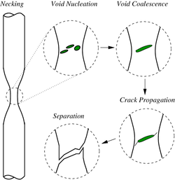 Schematic representation of the steps in ductile fracture (in pure tension)
In ductile fracture, extensive plastic deformation (necking) takes place before fracture. The terms "rupture" and "ductile rupture" describe the ultimate failure of ductile materials loaded in tension. The extensive plasticity causes the crack to propagate slowly due to the absorption of a large amount of energy before fracture.[9][10]
 Ductile fracture surface of 6061-T6 aluminum
Because ductile rupture involves a high degree of plastic deformation, the fracture behavior of a propagating crack as modelled above changes fundamentally. Some of the energy from stress concentrations at the crack tips is dissipated by plastic deformation ahead of the crack as it propagates.
The basic steps in ductile fracture are microvoid[11] formation, microvoid coalescence (also known as crack formation), crack propagation, and failure, often resulting in a cup-and-cone shaped failure surface. The microvoids nucleate at various internal discontinuities, such as precipitates, secondary phases, inclusions, and grain boundaries in the material.[11] As local stress increases the microvoids grow, coalesce and eventually form a continuous fracture surface.[11] Ductile fracture is typically transgranular and deformation due to dislocation slip can cause the shear lip characteristic of cup and cone fracture.[12]
The microvoid coalescence results in a dimpled appearance on the fracture surface. The dimple shape is heavily influenced by the type of loading. Fracture under local uniaxial tensile loading usually results in formation of equiaxed dimples. Failures caused by shear will produce elongated or parabolic shaped dimples that point in opposite directions on the matching fracture surfaces. Finally, tensile tearing produces elongated dimples that point in the same direction on matching fracture surfaces.[11]
The manner in which a crack propagates through a material gives insight into the mode of fracture. With ductile fracture a crack moves slowly and is accompanied by a large amount of plastic deformation around the crack tip. A ductile crack will usually not propagate unless an increased stress is applied and generally cease propagating when loading is removed.[6] In a ductile material, a crack may progress to a section of the material where stresses are slightly lower and stop due to the blunting effect of plastic deformations at the crack tip. On the other hand, with brittle fracture, cracks spread very rapidly with little or no plastic deformation. The cracks that propagate in a brittle material will continue to grow once initiated.
Crack propagation is also categorized by the crack characteristics at the microscopic level. A crack that passes through the grains within the material is undergoing transgranular fracture. A crack that propagates along the grain boundaries is termed an intergranular fracture. Typically, the bonds between material grains are stronger at room temperature than the material itself, so transgranular fracture is more likely to occur. When temperatures increase enough to weaken the grain bonds, intergranular fracture is the more common fracture mode.[6]
Fracture in materials is studied and quantified in multiple ways. Fracture is largely determined by the fracture toughness ( ), so fracture testing is often done to determine this. The two most widely used techniques for determining fracture toughness are the three-point flexural test and the compact tension test.
By performing the compact tension and three-point flexural tests, one is able to determine the fracture toughness through the following equation:

Where:
 is an empirically-derived equation to capture the test sample geometry
 is the fracture stress, and
 is the crack length.
To accurately attain , the value of  must be precisely measured. This is done by taking the test piece with its fabricated notch of length
  and sharpening this notch to better emulate a crack tip found in real-world materials.[13] Cyclical prestressing the sample can then induce a fatigue crack which extends the crack from the fabricated notch length of to . This value is used in the above equations for determining .[14]
Following this test, the sample can then be reoriented such that further loading of a load (F) will extend this crack and thus a load versus sample deflection curve can be obtained. With this curve, the slope of the linear portion, which is the inverse of the compliance of the material, can be obtained. This is then used to derive f(c/a) as defined above in the equation. With the knowledge of all these variables, can then be calculated.
Ceramics and inorganic glasses
[edit]
Ceramics and inorganic glasses have fracturing behavior that differ those of metallic materials. Ceramics have high strengths and perform well in high temperatures due to the material strength being independent of temperature. Ceramics have low toughness as determined by testing under a tensile load; often, ceramics have values that are ~5% of that found in metals.[14] However, as demonstrated by Faber and Evans, fracture toughness can be predicted and improved with crack deflection around second phase particles.[15] Ceramics are usually loaded in compression in everyday use, so the compressive strength is often referred to as the strength; this strength can often exceed that of most metals. However, ceramics are brittle and thus most work done revolves around preventing brittle fracture. Due to how ceramics are manufactured and processed, there are often preexisting defects in the material introduce a high degree of variability in the Mode I brittle fracture.[14] Thus, there is a probabilistic nature to be accounted for in the design of ceramics. The Weibull distribution predicts the survival probability of a fraction of samples with a certain volume that survive a tensile stress sigma, and is often used to better assess the success of a ceramic in avoiding fracture.
To model fracture of a bundle of fibers, the Fiber Bundle Model was introduced by Thomas Pierce in 1926 as a model to understand the strength of composite materials.[16] The bundle consists of a large number of parallel Hookean springs of identical length and each having identical spring constants. They have however different breaking stresses. All these springs are suspended from a rigid horizontal platform. The load is attached to a horizontal platform, connected to the lower ends of the springs. When this lower platform is absolutely rigid, the load at any point of time is shared equally (irrespective of how many fibers or springs have broken and where) by all the surviving fibers. This mode of load-sharing is called Equal-Load-Sharing mode. The lower platform can also be assumed to have finite rigidity, so that local deformation of the platform occurs wherever springs fail and the surviving neighbor fibers have to share a larger fraction of that transferred from the failed fiber. The extreme case is that of local load-sharing model, where load of the failed spring or fiber is shared (usually equally) by the surviving nearest neighbor fibers.[4]
Failures caused by brittle fracture have not been limited to any particular category of engineered structure.[5] Though brittle fracture is less common than other types of failure, the impacts to life and property can be more severe.[5] The following notable historic failures were attributed to brittle fracture:
Computational fracture mechanics
[edit]
Virtually every area of engineering has been significantly impacted by computers, and fracture mechanics is no exception. Since there are so few actual problems with closed-form analytical solutions, numerical modelling has become an essential tool in fracture analysis. There are literally hundreds of configurations for which stress-intensity solutions have been published, the majority of which were derived from numerical models. The J integral and crack-tip-opening displacement (CTOD) calculations are two more increasingly popular elastic-plastic studies. Additionally, experts are using cutting-edge computational tools to study unique issues such as ductile crack propagation, dynamic fracture, and fracture at interfaces. The exponential rise in computational fracture mechanics applications is essentially the result of quick developments in computer technology.[17]
Most used computational numerical methods are finite element and boundary integral equation methods. Other methods include stress and displacement matching, element crack advance in which latter two come under Traditional Methods in Computational Fracture Mechanics.
 Fine Mesh done in Rectangular area in Ansys software (Finite Element Method)
The finite element method
[edit]
The structures are divided into discrete elements of 1-D beam, 2-D plane stress or plane strain, 3-D bricks or tetrahedron types. The continuity of the elements are enforced using the nodes.[17]
The boundary integral equation method
[edit]
In this method, the surface is divided into two regions: a region where displacements are specified Su and region with tractions are specified ST . With given boundary conditions, the stresses, strains, and displacements within the body can all theoretically be solved for, along with the tractions on Su and the displacements on ST. It is a very powerful technique to find the unknown tractions and displacements.[17]
Traditional methods in computational fracture mechanics
[edit]
These methods are used to determine the fracture mechanics parameters using numerical analysis.[17] Some of the traditional methods in computational fracture mechanics, which were commonly used in the past, have been replaced by newer and more advanced techniques. The newer techniques are considered to be more accurate and efficient, meaning they can provide more precise results and do so more quickly than the older methods. Not all traditional methods have been completely replaced, as they can still be useful in certain scenarios, but they may not be the most optimal choice for all applications.
Some of the traditional methods in computational fracture mechanics are:
- Stress and displacement matching
- Elemental crack advance
- Contour integration
- Virtual crack extension
- ^ A simple load-controlled tensile situation would be to support a specimen from above, and hang a weight from the bottom end. The load on the specimen is then independent of its deformation.
- ^ A simple displacement-controlled tensile situation would be to attach a very stiff jack to the ends of a specimen. As the jack extends, it controls the displacement of the specimen; the load on the specimen is dependent on the deformation.
- ^
Cherepanov, G.P., Mechanics of Brittle Fracture
- ^ a b Degarmo, E. Paul; Black, J T.; Kohser, Ronald A. (2003), Materials and Processes in Manufacturing (9th ed.), Wiley, p. 32, ISBN 0-471-65653-4.
- ^ Lund, J. R.; Bryne, J. P., Civil. Eng. and Env. Syst. 18 (2000) 243
- ^ a b Chakrabarti, Bikas K. (December 2017). "Story of the Developments in Statistical Physics of Fracture, Breakdown and Earthquake: A Personal Account". Reports in Advances of Physical Sciences. 01 (4): 1750013. doi:10.1142/S242494241750013X. ISSN 2424-9424.
 Text was copied from this source, which is available under a Creative Commons Attribution 4.0 International License.
- ^ a b c d e f g h i Rolfe, John M. Barsom, Stanley T. (1999). Fracture and fatigue control in structures: applications of fracture mechanics (3 ed.). West Conshohocken, Pa.: ASTM. ISBN 0-8031-2082-6.
cite book: CS1 maint: multiple names: authors list (link)
- ^ a b c d e f g Campbell, F.C., ed. (2012). Fatigue and fracture: understanding the basics. Materials Park, Ohio: ASM International. ISBN 978-1-61503-976-0.
- ^ Inglis, Charles E. (1913). "Stresses in a plate due to the presence of cracks and sharp corners" (PDF). Transactions of the Institution of Naval Architects. 55: 219–230.
- ^ C. H. Chen; H. P. Zhang; J. Niemczura; K. Ravi-Chandar; M. Marder (November 2011). "Scaling of crack propagation in rubber sheets". Europhysics Letters. 96 (3) 36009. Bibcode:2011EL.....9636009C. doi:10.1209/0295-5075/96/36009. S2CID 5975098.
- ^ Perez, Nestor (2016). Fracture Mechanics (2nd ed.). Springer. ISBN 978-3-319-24997-1.
- ^ Callister, William D. Jr. (2018). Materials science and engineering: an introduction (8th ed.). Wiley. pp. 236–237. ISBN 978-1-119-40539-9. OCLC 992798630.
- ^ a b c d Ewalds, H. L. (1985). Fracture mechanics. R. J. H. Wanhill. London: E. Arnold. ISBN 0-7131-3515-8. OCLC 14377078.
- ^ Askeland, Donald R.; Wright, Wendelin J. (January 2015). The science and engineering of materials (Seventh ed.). Boston, MA. pp. 236–237. ISBN 978-1-305-07676-1. OCLC 903959750.
cite book: CS1 maint: location missing publisher (link)
- ^ An improved semi-analytical solution for stress at round-tip notches, a closer look
- ^ a b c Courtney, Thomas H. (2000), Mechanical behavior of materials (3nd ed.), McGraw Hill, ISBN 1-57766-425-6.
- ^ Faber, K. T.; Evans, A. G. (1 April 1983). "Crack deflection processes—I. Theory". Acta Metallurgica. 31 (4): 565–576. doi:10.1016/0001-6160(83)90046-9. ISSN 0001-6160.
- ^ Pierce, F. T., J. Textile Indust. 17 (1926) 355
- ^ a b c d Anderson, T. L. (2005). Fracture mechanics: fundamentals and applications (3rd ed.). Boca Raton, FL. ISBN 978-1-4200-5821-5. OCLC 908077872.
cite book: CS1 maint: location missing publisher (link)
- Dieter, G. E. (1988) Mechanical Metallurgy ISBN 0-07-100406-8
- A. Garcimartin, A. Guarino, L. Bellon and S. Cilberto (1997) "Statistical Properties of Fracture Precursors". Physical Review Letters, 79, 3202 (1997)
- Callister Jr., William D. (2002) Materials Science and Engineering: An Introduction. ISBN 0-471-13576-3
- Peter Rhys Lewis, Colin Gagg, Ken Reynolds, CRC Press (2004), Forensic Materials Engineering: Case Studies.
| |
| Chemical weathering |
|
| Physical weathering |
|
| Related topics |
|
| |
| Patterns |
|
|
| Causes |
|
| People |
|
| Related |
|